
Weather Station: Stage 2
15 June 2026
Stage 2: Mo' Sensors, Mo' Problems
If you've ended up here, please know this is a series. The remainder of the articles are listed below:
Refactoring for Future
At the end of Stage 1, main.c was sitting at about 200 lines with a single sensor, and I'd already figured that it was going to get unwieldy. Stage 2 brings three new sensors online:
- VEML6075 for UV
- BH1750 for ambient light
- AS3935 for lightning
If I just kept bolting code onto the bottom of that file, I'd end up with 600 lines of spaghetti and a strong urge to start the whole thing again. Or have Claude refactor it.
So before plugging anything new in, I broke the firmware apart.
The idea is straightforward: every sensor becomes its own .c/.h module that implements the same interface. An init() function and a read() function. That's it. The BMP280 driver doesn't know the WiFi exists. The transport layer doesn't know what sensors are connected. And main.c becomes a short loop that walks through a list of registered sensors, collects their readings, and hands them to transport for transmission.
1static const sensor_driver_t *sensors[] = {
2    &bmp280_driver,
3    &veml6075_driver,
4    &bh1750_driver,
5    &as3935_driver,
6};
Adding a new sensor now means writing a .c file that follows the pattern, adding one line to this array, and updating CMakeLists.txt. No touching the network code. No touching other sensors. No 600-line main.c. I'm actually quite pleased with how clean it ended up. main.c is about 50 lines, and most of that is the loop and some printf statements.
The I2C helpers also got pulled into their own module (i2c_bus.c), since multiple sensors share the same bus. The BMP280 needs standard register reads. The VEML6075 needs 16-bit register writes. The BH1750 uses bare command bytes with no register address at all. Rather than each driver reimplementing I2C low-level operations, they all call shared helpers and just pass their own device address. One bus, four devices, no duplication.
The File Layout
The project now looks like this:
1weather-station/
2├── CMakeLists.txt
3├── lwipopts.h
4└── src/
5    ├── config.h          all pins, credentials, timing
6    ├── sensor.h          the common driver interface
7    ├── i2c_bus.h/.c      shared I2C helpers
8    ├── bmp280.h/.c       temperature + pressure
9    ├── veml6075.h/.c     UV
10    ├── bh1750.h/.c       ambient light
11    ├── as3935.h/.c       lightning
12    ├── transport.h/.c    WiFi + HTTP POST
13    └── main.c            just the loop
Everything sensor-specific is self-contained. All magic numbers live in config.h. The transport layer dynamically builds JSON from whatever readings it receives, so the server payload grows automatically as sensors get added. After this stage, the JSON hitting the server looks like this:
1{
2  "temperature":23.85,
3  "pressure":1003.43,
4  "uva":12.30,
5  "uvb":8.75,
6  "uv_index":0.42,
7  "light_lux":1850.00,
8  "lightning_km":0.00
9}
Seven fields from four sensors, and nobody had to touch the HTTP code to make that happen.
The Bug That Was Always There
With the refactoring done and the BMP280 confirmed working in its new modular home, I ran it for a while to make sure nothing had broken. It worked. First reading, WiFi connect, POST OK. Then it hung.
Every time. Boot, one successful POST, hang.
Irritating.
My first instinct was that the transport_reset() function was the problem. After each POST, the original code was doing a full trash and re-initialisation of the CYW43 WiFi driver. I took the nuclear approach and swapped it for a simple WiFi disconnect (cyw43_wifi_leave), which helped, but the hang came back after a few cycles.
What was actually happening was a bit more subtle and took me a while to understand. The HTTP POST state (a struct tracking whether the request completed or errored) was a local variable on the stack inside transport_send(). The lwIP callbacks held a pointer to it via tcp_arg(). When on_sent fired and set complete = true, the while loop exited, the function returned, and the struct went out of scope. But the TCP connection was still alive, being closed in the background by lwIP. If any further callback fired (processing the server's response, a close timeout, a retransmit), it would write through that dangling pointer into whatever happened to be on the stack at that point.
What a gift for software development I clearly have. Delightful little mess.
There were actually three issues stacked on top of each other:
- The dangling pointer: Fixed by cleaning up the TCP PCB (detaching all callbacks and aborting the connection) before
transport_send()returns, while the state struct is still alive on the stack. - No receipt handler: The server sends back a
200 OKresponse body, but there was notcp_recvcallback to consume it. The receive buffer fills, TCP advertises a zero window, and the close handshake stalls because the server can't send its FIN. - No output flush:
tcp_write()queues data in a send buffer, but without callingtcp_output()afterwards, the data can sit there waiting for lwIP's next poll cycle. Most of the time it works. Sometimes it doesn't. Hence the intermittent dropped readings.
Once all three were fixed, the transport became rock solid. I left it running overnight and every single reading made it to the server. The kind of reliability that should have been there from Stage 1, if I'm being honest, but I didn't understand lwIP's callback model well enough at that point to see the problem. Truth be told, I don't understand many of the nuances of this stuff, but I feel like I'm learning a lot - which is addictive.
The VEML6075
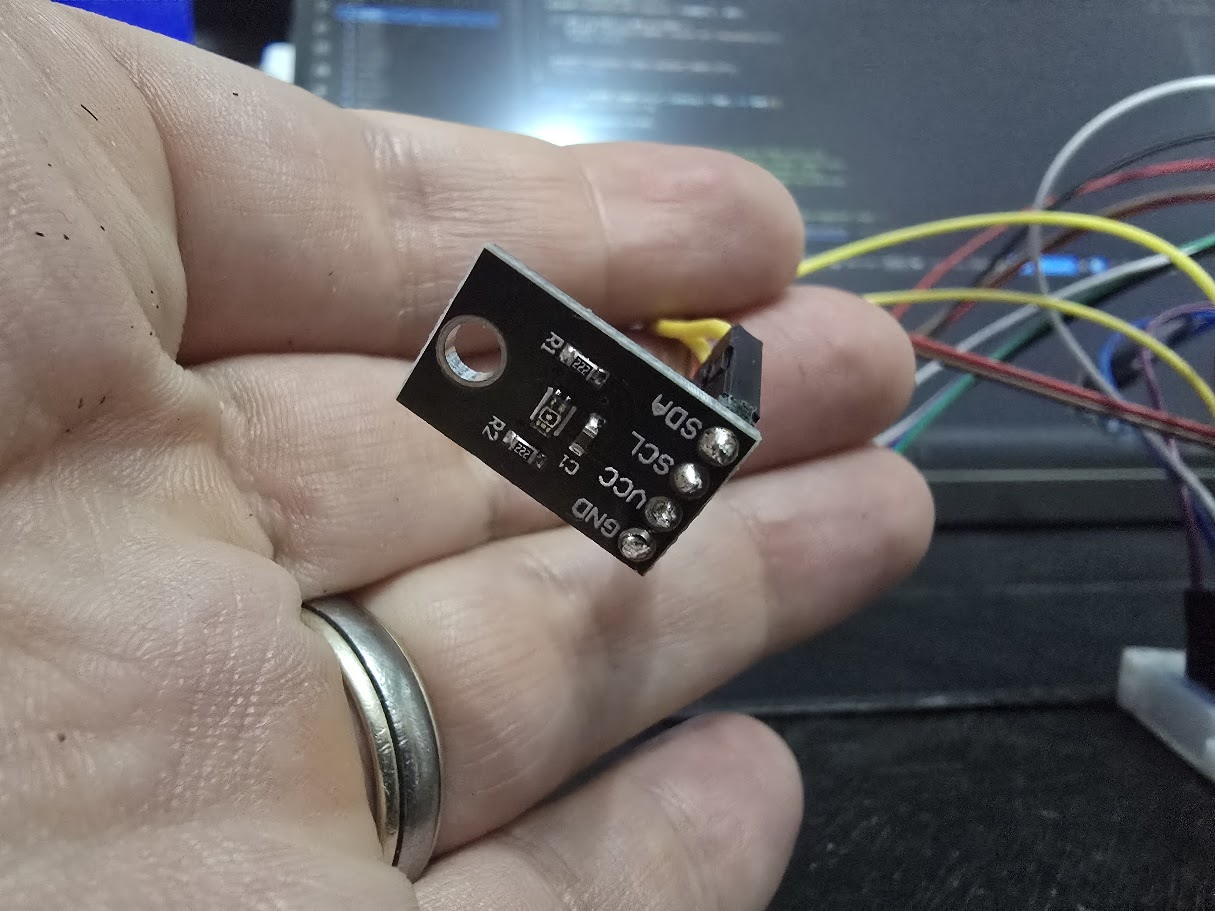
This was the one that "just worked". The VEML6075 was refreshingly uneventful. Four wires (VCC, GND, SDA, SCL), same I2C bus as the BMP280, address 0x10 so no conflicts. Plugged it in, flashed the firmware, and it started returning UVA, UVB, and UV Index readings immediately.
The sensor uses active force mode:
- Trigger a measurement
- Wait 120ms for integration
- Read the raw values
- Apply Vishay's compensation coefficients.
The UV Index calculation is a weighted combination of compensated UVA and UVB values. At 11pm indoors, everything read zero. Which is correct. I will take the wins )(including zero risk of sunburn from my office lamp) wherever I can get them.
The only thing worth noting is the compensation. The VEML6075 has two extra channels (UVCOMP1 and UVCOMP2) specifically for subtracting out visible and IR contamination. Without them, indoor lighting would generate phantom UV readings. The maths is in the datasheet, and it boils down to four multiplication-subtraction operations and a weighted average. Bosch's BMP280 compensation formulas were significantly more painful.
The BH1750
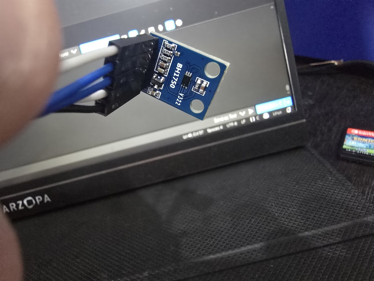
If the VEML6075 was the well-behaved child, the BH1750 had left home and was smoking meth aged 11.
It started promisingly. Same I2C bus, address 0x23 (with the ADDR pin tied to GND), five wires including the address pin. First boot, the init printed "ready", the first reading came back, and I thought I was done. I cover the sensor 0. I expose it to lamplight 100. It sat about 40 most of the time and then I went to bed.
The following evening, every reading was 426.67 lux. All of them. Didn't matter if I covered the sensor with my finger. Didn't matter if I turned the lights off. 426.67. Always 426.67.
426.67 lux (as Gemini helpfully informed me) is raw value 512 (0x0200) divided by 1.2. It's a suspiciously round binary number, and it turns out it was just the small issue that the sensor wasn't actually taking any measurements at all.
I went through a whole progression of fixes. I tried powering the sensor on before each one-time measurement. I tried switching from one-time mode to continuous mode. I added diagnostic prints that showed the raw I2C return values and buffer contents. The diagnostics finally showed what was happening: ret=-1 buf=[0xFF, 0xFF]. The I2C read was failing completely. The sensor was NACKing. It wasn't on the bus.
That meant the "ready" at boot was a lie. The BH1750 doesn't have a device ID register like the BMP280 or VEML6075, so the init was just firing commands into the void, printing "ready", and hoping for the best. I added a proper presence check, sending the power-on command using a timeout-based I2C write and checking the return value. If the sensor doesn't ACK, init fails immediately and you know the wiring is wrong, not the code.
Then I did an I2C bus scan to find what addresses were actually responding. The scan found the VEML6075 at 0x10, and then hung. Permanently. Something on the bus was ACKing an address but then holding the clock line, and once the bus locked up, no other sensor could communicate either. The BMP280 stopped responding too. Everything was down.
Then, I pulled the BH1750 off the breadboard, and the other sensors came back to life immediately.
The diagnosis, after an embarrassing amount of software debugging: a dodgy jumper wire. The ADDR pin wasn't making reliable contact. When it floated, the sensor's I2C state machine went haywire, sometimes ACKing at random addresses, sometimes holding the bus hostage. I replaced every jumper wire going to the BH1750, reseated it in a fresh section of the breadboard, and it worked immediately. Real readings. Varying with actual light conditions. Responsive to a torch. Responsive to covering the sensor. The 0.00 lux at midnight that I'd been chasing for hours was, in fact, correct, because it was midnight.
The driver now uses continuous measurement mode (the sensor stays active and refreshes every 120ms) with timeout-based I2C reads. If the bus acts up, the read fails gracefully and the main loop skips that sensor for the cycle rather than hanging the entire system. It's the kind of defensive coding I should have been doing from the start, but you don't learn to check return values until you've spent a night staring at 426.67.
Lesson learned: breadboard connections are a lie. They look fine. They feel firm. They work for an hour and then they don't. When a sensor behaves erratically and you've exhausted every software explanation, swap the jumper wires before you turn into a jumper yourself. Also, if a sensor doesn't have a device ID register, verify its presence during init by checking whether the I2C write is ACKed. Silent failures are the worst failures, and I already knew that from Stage 1.
The AS3935
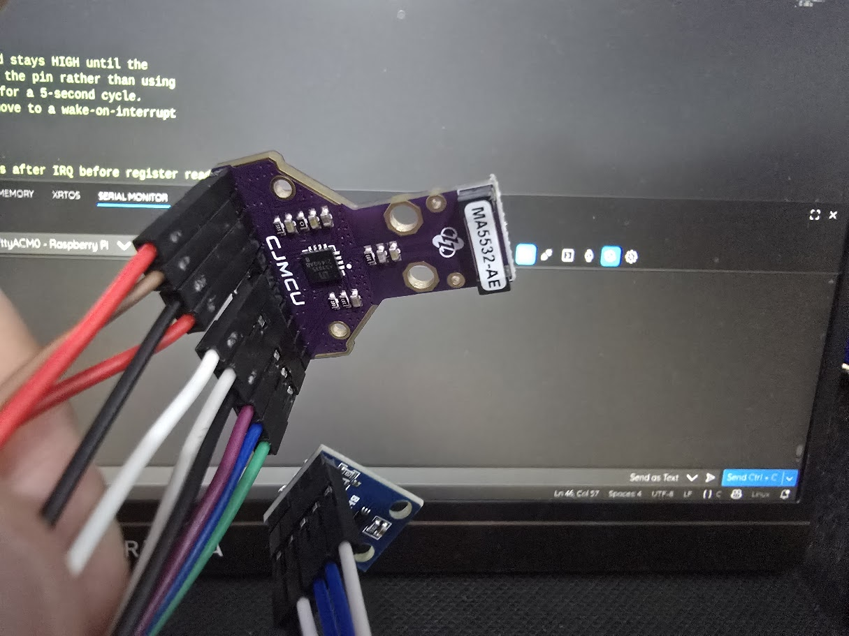
The lightning detector. The one I described in Stage 0 as "the eccentric one." It hasn't done anything to change that assessment.
The AS3935 module I have exposes eleven pins, because it supports both SPI and I2C. In I2C mode, five of those pins just get tied to 3V3 (SI for interface selection, CS to deselect SPI, A0 and A1 for address configuration, EN_V to enable the chip). MOSI acts as SDA. MISO is left unconnected. SCL is SCL. IRQ goes to GP6. That's nine wires plus a floater. It looks complex on paper, but once you realise that five of them are just "connect to the power rail and forget about it", it's not much worse than the other sensors.
The driver polls GP6 (the interrupt pin) each cycle. When the AS3935 detects an event, IRQ goes high and stays high until the interrupt register is read. So even with a 5-second cycle, events that happened between readings aren't lost. If the event was lightning, the driver reads the estimated distance (1-40 km). If it was a disturber or noise, it logs it and moves on. The lightning_km reading in the JSON is 0 when nothing was detected.
One thing I wasn't prepared for was the electromagnetic noise. The AS3935 isn't listening for audible noise. It's detecting RF interference in the 500kHz band, and a desktop PC is absolutely screaming at that frequency. The serial output was a wall of [AS3935] Noise level too high. messages. The fix was raising the noise floor threshold from the default (level 2) to level 5. That quietened it down for indoor testing. When it moves outdoors, away from switch-mode power supplies and USB cables, I'll drop it back down for better sensitivity to distant strikes.
The polling approach has a known limitation: the interrupt register auto-clears after 1.5 seconds. With a 5-second cycle, there's roughly a 30% chance of catching any individual strike's data. During a storm, with many events over minutes, that's plenty. When I move to longer sleep intervals in Stage 5, I'll need to switch to a GPIO interrupt that captures the distance immediately and holds it for the next read. There's a comment in the driver flagging that for future me. I will definitely forget it's there.
What I Actually Learned
Stage 2 was supposed to be the "just add more sensors" stage. Wire them up, write the drivers, move on. What it actually involved was a ground-up firmware refactor, a TCP use-after-free bug, a sensor that lied about being ready, a bus lockup caused by a loose jumper wire, and a lightning detector that thought my desktop PC was a thunderstorm.
It looks like an absolute disaster - so the cable management fiends on r/CableManagement might want to look away:
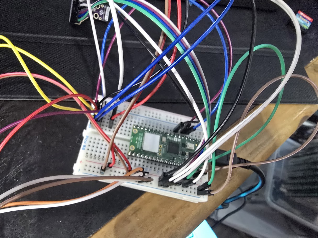
A few things I'll carry forward:
- Refactor before you scale. Breaking main.c into modules before adding sensors was the best decision of the stage. Every debugging session was easier because each sensor was isolated.
- lwIP callbacks are not optional reading. If you're using raw TCP on the Pico W, understand the PCB lifecycle. Know when the state struct goes out of scope. Add a receive handler. Flush the send buffer. The callbacks are not suggestions.
- Verify sensor presence during init. If the sensor has a chip ID, check it. If it doesn't, check the I2C ACK. Don't print "ready" if you haven't confirmed the device is actually there.
- Use timeouts, not blocking calls.
i2c_read_blockingwill hang forever if a sensor holds the bus.i2c_read_timeout_usgives you a graceful failure instead of a brick. - Swap the wires. When the software is right and the readings are wrong, the hardware connection is the most likely culprit. Especially on a breadboard.
What's Next
Stage 3: the data pipeline. Getting readings off the Pico and into something useful on the server side. This is the bit where my actual day job skills come in, so with any luck the blog post will be shorter and contain significantly fewer confessions. No promises.